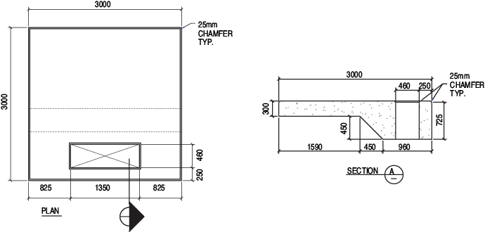
Transformer Pad125m H x 1549mm x 1549mm. Primary conduits must be centered in the window.
Transformer Pads
LCS geomembrane liners are durable enough to last and in some cases can be installed within a day or two weather permitting.
. A sump pit with cover is to be placed in one corner of vaults located. Flat bottom construction to facilitate leveling and eliminate sinking common in waffle bottom pads. Back fill and compact the area around the transformer pad to achieve the proper grade.
Final pad design dimensions for the invertertransformer pad will be determined based on the final equipment selection and approval by the electrical inspector andor utility representative. Precast pads do not have cut off walls. TRANSFORMER PAD DESIGN General Requirements None C721-08-091-600-6001 102709 Projection to ground considered as floor area.
Reinforced Concrete Analysis and Design. Wood float finish leaving no depressions. Contact us if you have any inquiries about our transformer pads or to request a quote.
Integrated clip design allows for a wide adjustment range to accommodate multiple cabinet sizes. Transformer Pad20m H x 1880mm x 1880mm. From small stabilizing pads to large transformer foundations Oldcaslte Infrastructure equipment pads are durable and convenient foundations for your equipment needs.
42 Olson Precast O-RS-13. Hydro One DL 3193C02. Smooth surface application is standard.
Youll find that they work well. Eversource Concrete Transformer Pad Types. Back of pad must be 36-inch minimum distance from building line including any roof overhang.
Transformer Pad92m H x 1545mm x 1650mm. Often being constructed in less than a day these pads are readily available for immediate installation without waiting for curing like pour-in-place alternatives. GENERAL 11 Considerations.
See table 54 for concrete thickness t. An integral transformer leak basin can be used in lieu of a dike. D - Concrete Standards General Outline and Reinforcement Notes 2.
48 b 2 ea. Concrete Pad for Three-Phase Loop-Style Greenbook Pad-Mounted Transformers Rev. 27 c 5 ea.
RS-13 RS-19 AND RS-28 TRANSFORMER PADS. Fiber Reinforced Concrete Transformer Pads. Concrete Footing Foundation and Pad Installation 1.
Was in a building this week where all the transformers had been anchored straight to the floor this looked really odd to me every transformer Ive ever set needed to be on a concrete pad and Ive hung a few from strut as well but never just set it right on the ground. Hydro Ottawa UCS 0001. 12-01-19 045292 Page 5 of 8 Pad Arrangements for Style IIA IIB IIC IIF and IIH Transformers Notes 1.
We have become a leading supplier of transformer mounting solutions serving Utilities throughout North America with our unique blend of Fiber Reinforced Concrete. By lining a transformer pad or substation the ground is safe from any mineral oil. A 6-inch concrete dike is to be cast onto the floor to prevent leaking transformer oil from escaping vault.
Design drawings pertaining to a vault installation shall be uniformly prepared and sealed by the Customers design professional. Concrete sump design Sumps and depressions must be constructed from a monolithic pour of the concrete used in the floor of the mixing and loading pad or secondary containment structure. Use as reference for required clearance area.
I called up a buddy and he seemed to think that it wasnt something that was. A 4 ea. Since 1972 DiversiTech has developed proprietary technologies in advancing the engineering design and functionality of equipment pads across multiple industry segments.
We can discuss your. Fully contained substation applications can require a great deal of detail work. 157m H x 1880mm x 1880mm OD Kingston Hydro K03-03-123.
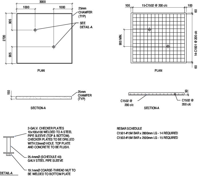
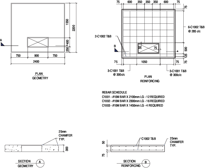
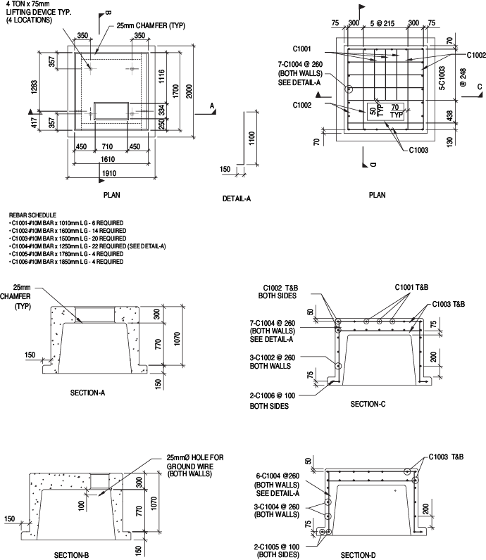
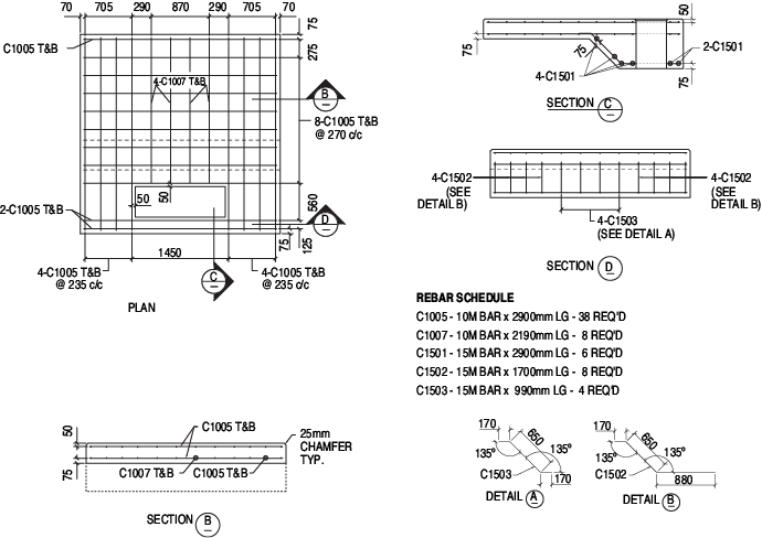
Rebar shall be a minimum 4 and placed into the above drawing according to the rebar schedules. Place the transformer equipment on the pad and bolt it down. Each pad will be minimum of 8 inches thick reinforced concrete.
Minimum concrete cover over reinforcing steel is 2 unless otherwise noted. Connections to the transformer as specified in Sections IV and V. B Standard Designs Sitework Typical Water Crossing 4.
A Raft foundation is considered for a 132kV Transformer. Illustration 1 - page 4. Fitting the liner to concrete walls pads and pipe.
Minimum Clearance To Openings Other Than Natural Garage Vents Figure 1. They are designed to be. B The bottom of the raft is at a depth of 10m from existing ground surface.
137m H x 1549mm x 1549mm E5. Manufacturers approval assembly drawings relating to the physical arrangement of the. Chapter 6 Design of Pad Foundations 60 NOTATION Point on surface of concrete to nearest face of a bar Length of a side of a rectangular pad foundation Area of tensile reinforcement Area of tensile reinforcement to resist bending about x-axis Area of tensile reinforcement to resist bending about y-axis Width of.
B Design Standards Unified Soil Classification 5. Transformer Base and Pad. Place the transformer pad on the base.
D - Concrete Standards General Outline and Reinforcement Notes 3. 1 Ask a vague open ended question to a website visited by a lot of experienced engineers who have very little patience for vague open ended questions. C Soil bearing capacity is considered 9004 kNm2 minimum value from BH-4 BH-5 BH-7.
Transformer pads shall be placed at least 10ft radially from all doors including garage. Pad unistruts shall be hot dip galvanized steel type P2000HG x 2-12. Pad cable slot shall.
Conduits shall not protrude above top of transformer pad. Single Phase Sector Cabinet 53125 Three Phase Sector Cabinet 53128 Concrete Pullbox H-10 for Grassy Areas NH Splice Pit 25 to 75 KVA Transformer Pad 53102 100 to 250 KVA Transformer Pad 53102L 75 to 500 KVA Transformer Pad 53111 750 to 2000 KVA Transformer Pad 53113. Concrete detail for mixing and loading pad floor with integral edge curb.
Compaction Backfill placed under a transformer pad or mounting pit shall be compacted in 12 lifts to achieve 95 compaction. Ensure any cablesconduits are positioned in the correct cable entrance holes. 2 Wait for the fun to ensue.
Manufacturers proposed specifications for the electrical service equipment. The basin is to be sized large enough to contain the liquid contents of the transformer. Secondary conduits shall be grouped towards the front of the pad.
Reinforcing steel ATSM-A615 grade 60 place approximately 6 from each other and securely tied together. TRANSFORMER PADS ALL DIMENSION IN INCHES A 104 REINFORCING BARS 13 4 98 SECONDARY C 3 4. Transformer Foundation Design using Reinforced Concrete SlideRuleEra Structural 22 Feb 16 2256 Keep in mind that the Risk Category Table 15-1 of ASCE 7-10 should be either Category III Buildings and other structures not included in Risk Category IV with potential to cause a substantial economic impact andor mass disruption of day.
Splay openings shall remain open for future conduits. The customer shall furnish install own and maintain the concrete footing foundation pad ground rods and all wiring.
Transformer Pads
![]()
Transformer Pads Lhv Precastlhv Precast
Transformer Pads

Transformer Pads

Transformer Pads
![]()
Transformer Pads Lhv Precastlhv Precast
Transformer Pads
Transformer Pads
0 comments
Post a Comment