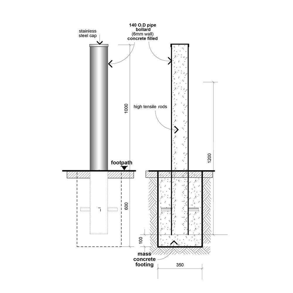
More details and detailed safety calculations can be provided. Street bollards are a part of a traffic calming.
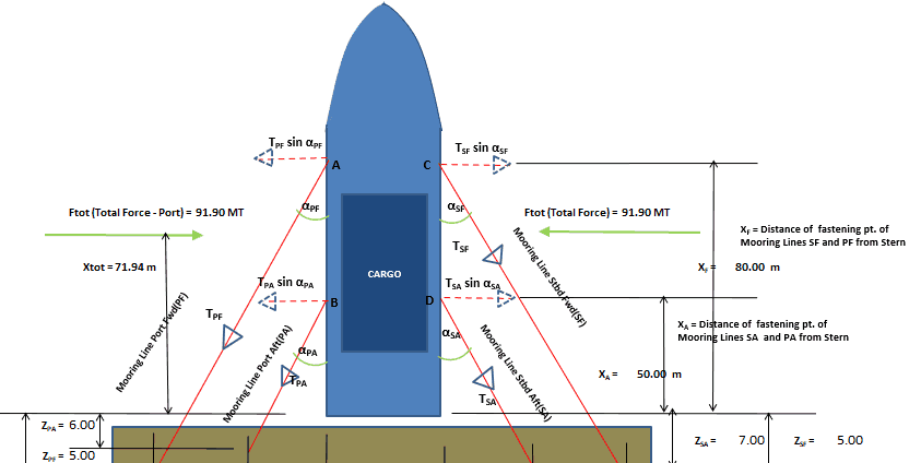
Vessel With Stern On Quay A Simplified Method For Mooring Design Thenavalarch
Generally design of a bollard should have a thicker diameter at the top head tip of the structure to make it harder for the mooring lines to escape accidentally.
. Calculate based on the size and geometry of the vessel the total environmental forces on. Bollard system as a protective device for your storefront or other location it is critical that the foundations for each bollard system be designed in accordance with the expected loads. Structural characteristics of the MOT including type and configuration of mooring fittings such.
Sidewalk safety and traffic calming. Assuming Bollards and Fenders are. International Standard Organization 1977.
This article provides the Mooring and berthing load calculation on Bollards and Fenders. Steel bollards which provide high impact resistance but require regular painting to prevent corrosion. Engineering calculations are provided with bollard systems describing bolt group pullout forces shear loadings and bolt tensions.
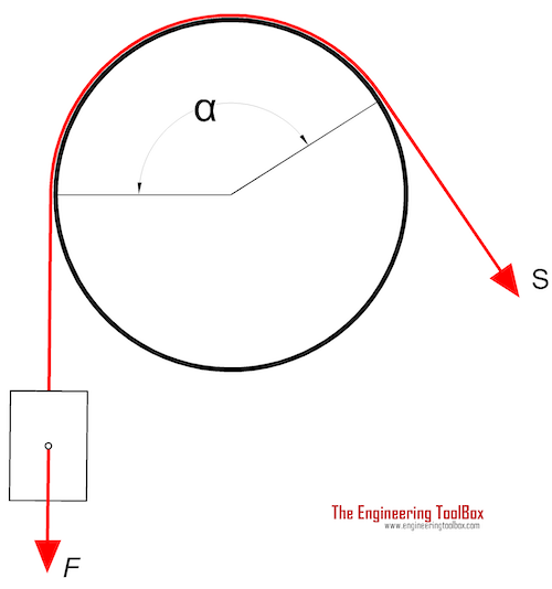
Mooring System Design and Analysis. 62 Mooring Lines Hardware and Equipment 63 Wind Forces 64 Current Forces 65 Standoff Forces and Passing Vessel Effects 66 Wave Loads and Vessel Motions 67 Analytical. Now we can delineate the steps for performing Required Bollard Pull calculations for towing a vessel as follows.
By Rahul Kanotra Consultant Naval Architect. The shape of Trelleborg bollards has been refined with finite element techniques to. WHARF MOORING SYSTEM DE PHILOSOPHY This article is to provide the Mooring and berthing load calculation on Bollards and Fenders.
Get the environmental data for the berth wind wave current tide etc. Changes to shore mooring points and bollard strength in Section 1461 to 1464. For wind force the formula is F wind 12 x C wind x ρ wind x V wind2 x A wind where C wind is the coefficient of wind force ρ wind is the density of air V wind is the wind.
ISO-3913 shipbuilding-welded steel bollards. The existing condition of the MOT shall be used in the mooring analysis see Section 3102F. Line position safety factor on yield test load notes double bollards per iso 3913 single rope mooring forces calculator port stbd on quay www thenavalarch com and to design a mooring.
Place bike bollards 3 to 5 feet apart measuring from the furthest extension of the bike locking arms. Once a mooring system for the vessel at the berth has been chosen for given position of the vessel the change in length of each mooring line with respect to its initial un. As the offshore industry moves towards greater technological advancements one.
Sections 1048 1264 and 1465 to 1466 have been moved from Guidelines for Load-outs 0013ND and. Ultimate strength assessment of mooring bollards and their foundation structures TEAM 2006 133-143. Step 1 Determine the environmental parameters Open Ocean.
Assuming Bollards and Fenders are installed at Piles Forces can be transferred to Piles for.
Bollard Forces
How To Design A Marine Bollard Anchorage Into Concrete Lasopatropical

Bollard Strength Check Spreadsheet Www Thenavalarch Com Boat Design Net

Bollard Requirement Pdf Rope Strength Of Materials

Pdf Ultimate Load Capacities Of Mooring Bollards And Hull Foundation Structures

Pdf Ultimate Load Capacities Of Mooring Bollards And Hull Foundation Structures

Ultimate Load Capacities Of Mooring Bollards And Hull Foundation Structures Sciencedirect
2
0 comments
Post a Comment